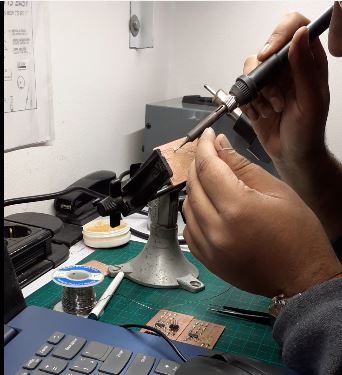
3. Soldering
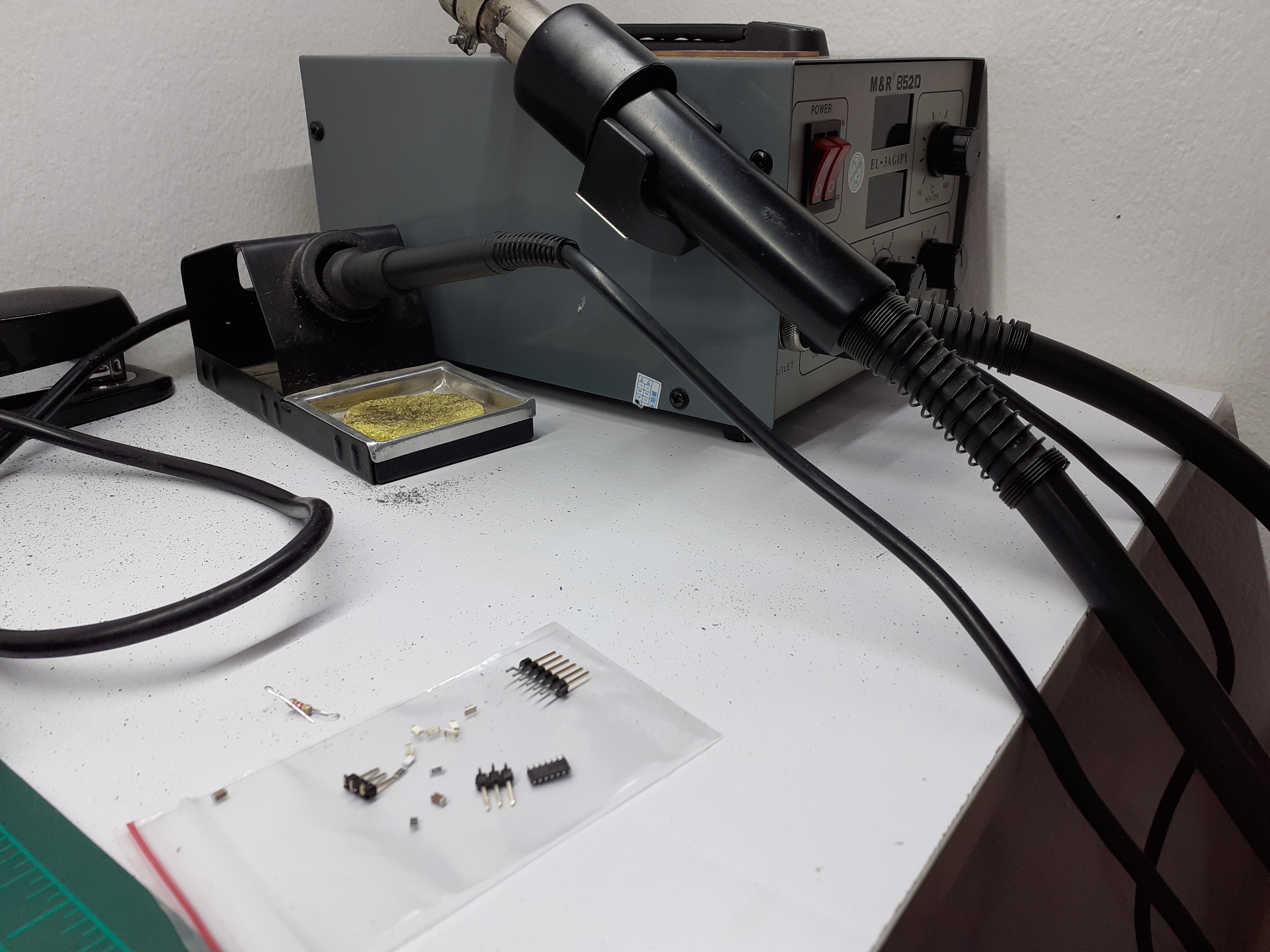
Required Tools for Soldering:
- Soldering Iron
- Solder
- Gift
- Digital multimeter
- Flux
- Spong damped
- cutter/wire cutter.
Required Components to be soldered:
- red LEDs x 6
- ATTINY 44 x1
- ISP Header 3p Male x2
- FTDI Header & FTDI programmer x1
- Capacitor 1uf x1
- Capacitor 0.1uf x1
- Resistor 10K x1
- Resistors 499 ohm x3
- ISP Header 6p Male x1
- Small wires (used legs of the resistors) x3
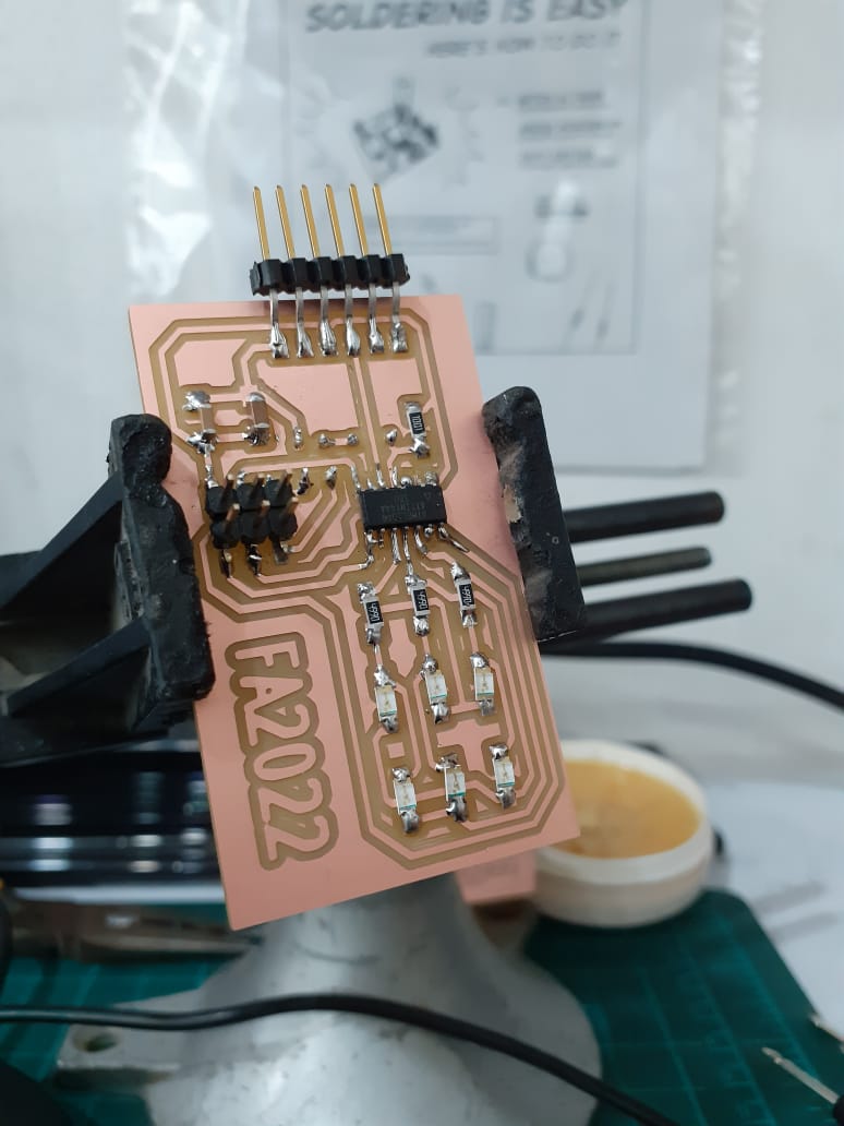
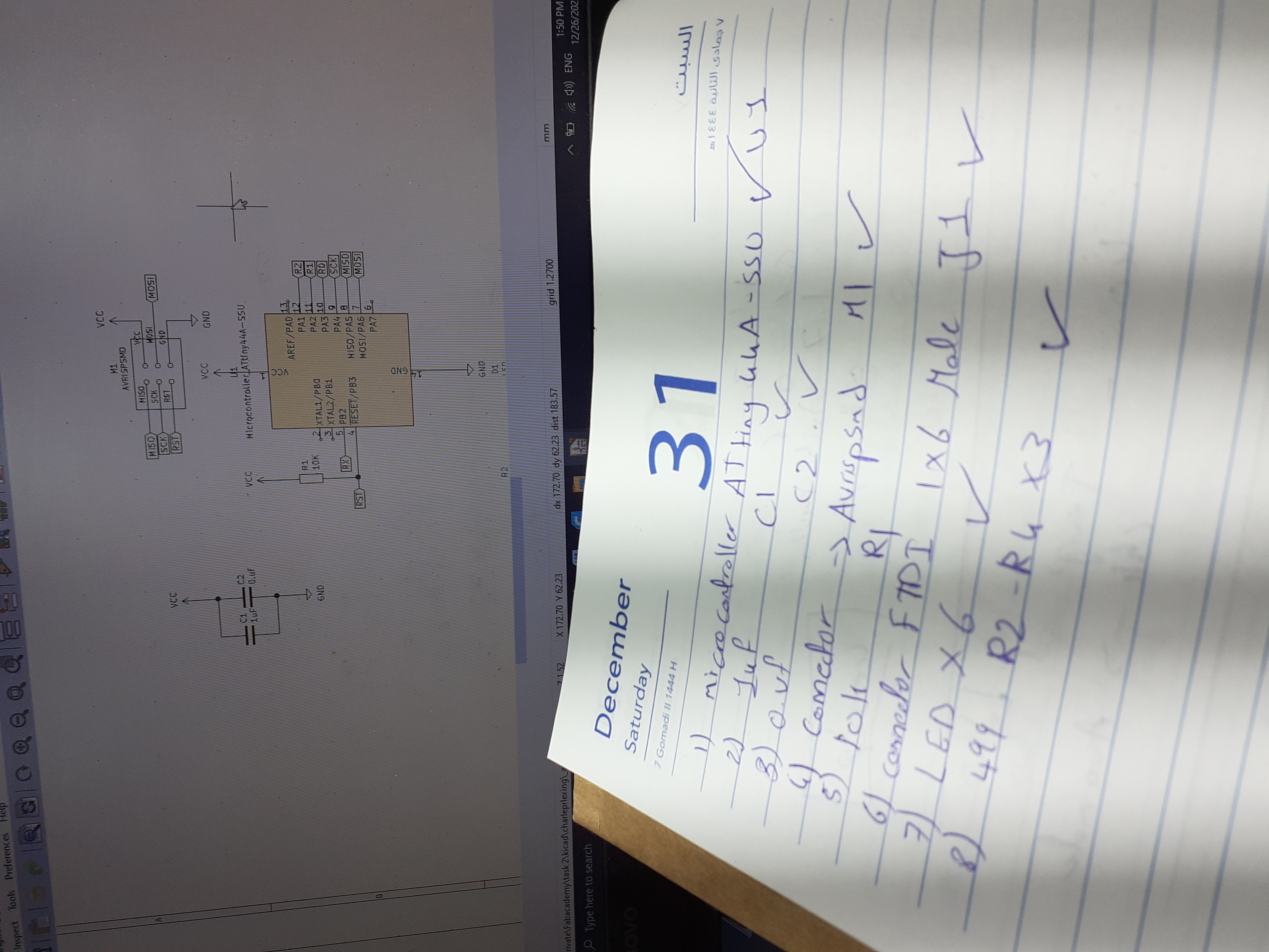
All components can be listed from schematics.
- Make sure that the orientation of the components is the same as in the design.
- Start by adding some solder on the pads then with gifts hold the component on that spot and heat it again to melt and place the component right.
- For LEDs, match the cathode in the design to the green strip on the physical component.
- For the Microcontroller, there is a notch that marks pin number 1.
- Resistors and ceramic capacitors can be soldered in any direction as they are indifferent to their orientation.
- For easy soldering, solder the PCB starting with from the centre to out and with smaller components then larger ones. So start with attiny then move to resistors, capacitors and leds. Finally isp pins and connecting wires.
Important note: do not heat the component for more than 5 seconds to avoid burning it.
Check the connections after each solder with a digital multimeter for accurate results.