2. Machining
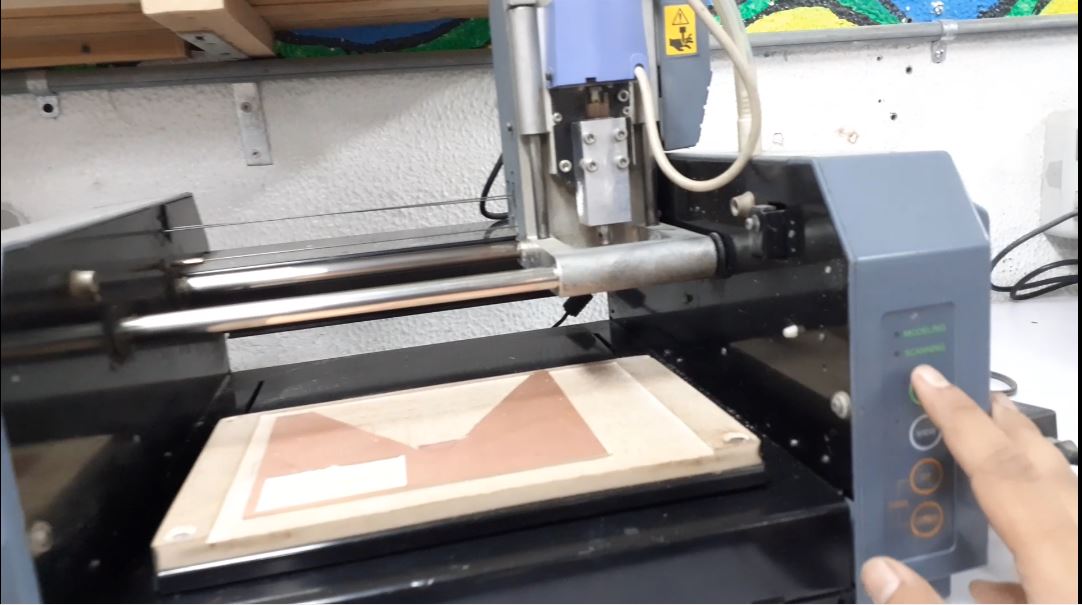
I will be using the Roland Modela mdx-20 A.K.A fab modela milling machine, by using fab modules.
This process will be done in the lab(Fab lab egypt), that is why it was not included in the previous step.
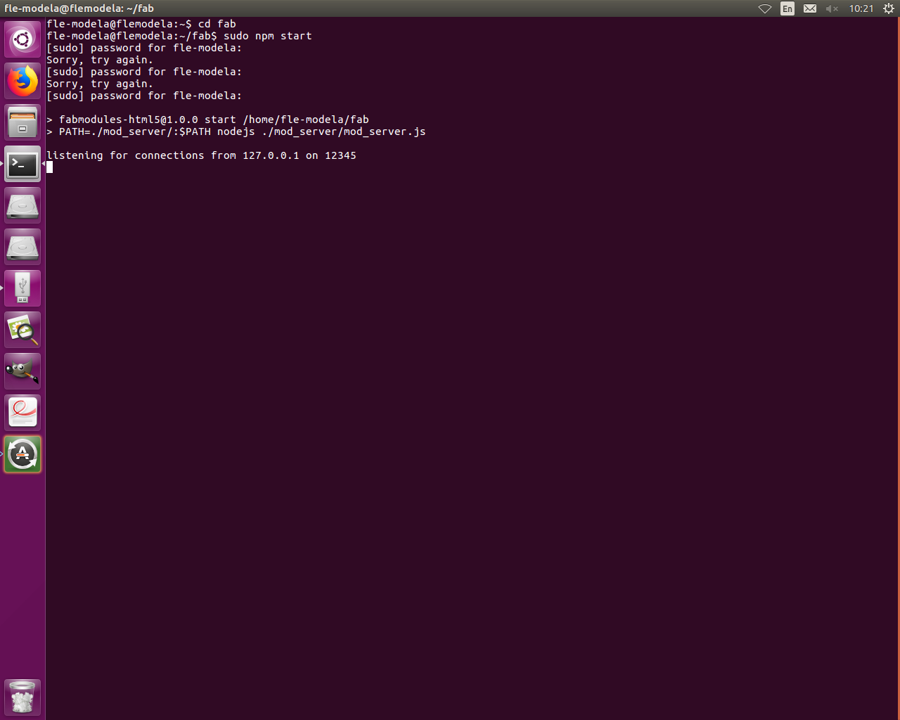
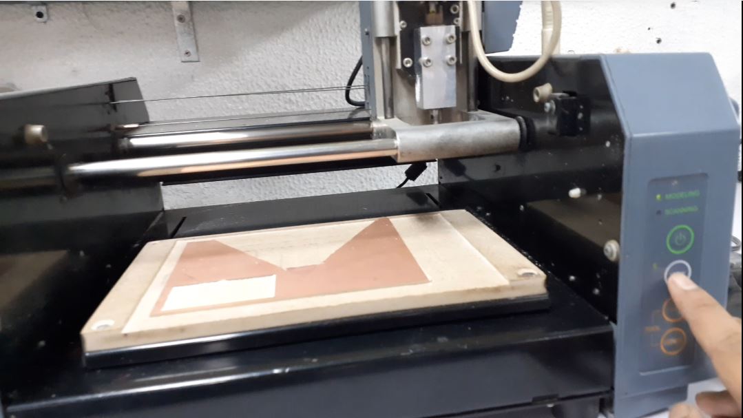
- On the computer beside the milling machine, open the command terminal and write these sentences. Also open the machine to make connection better by pressing the On button on the machine. (open image)
Cd fab (then press enter)
Sudo npm start (can add fab or just press enter) .
It will ask for password, kindly contact any fab specialist to assist in this matter.
Wait until it says listening….(an IP address will be written here copy it).
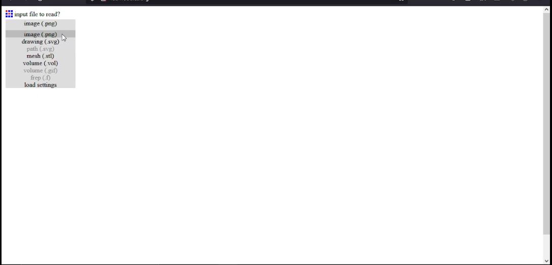
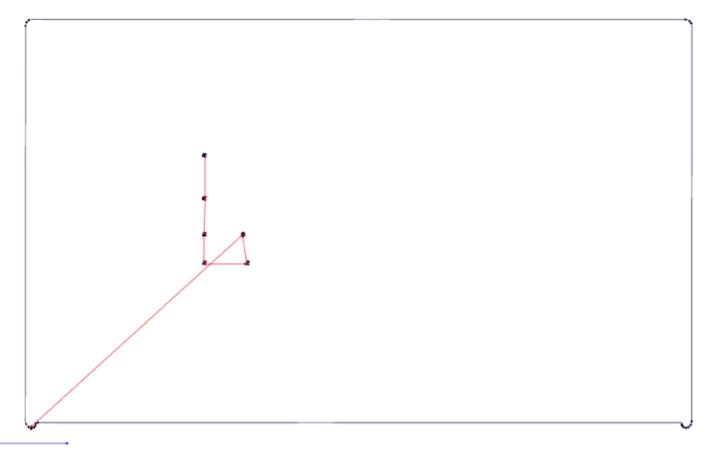
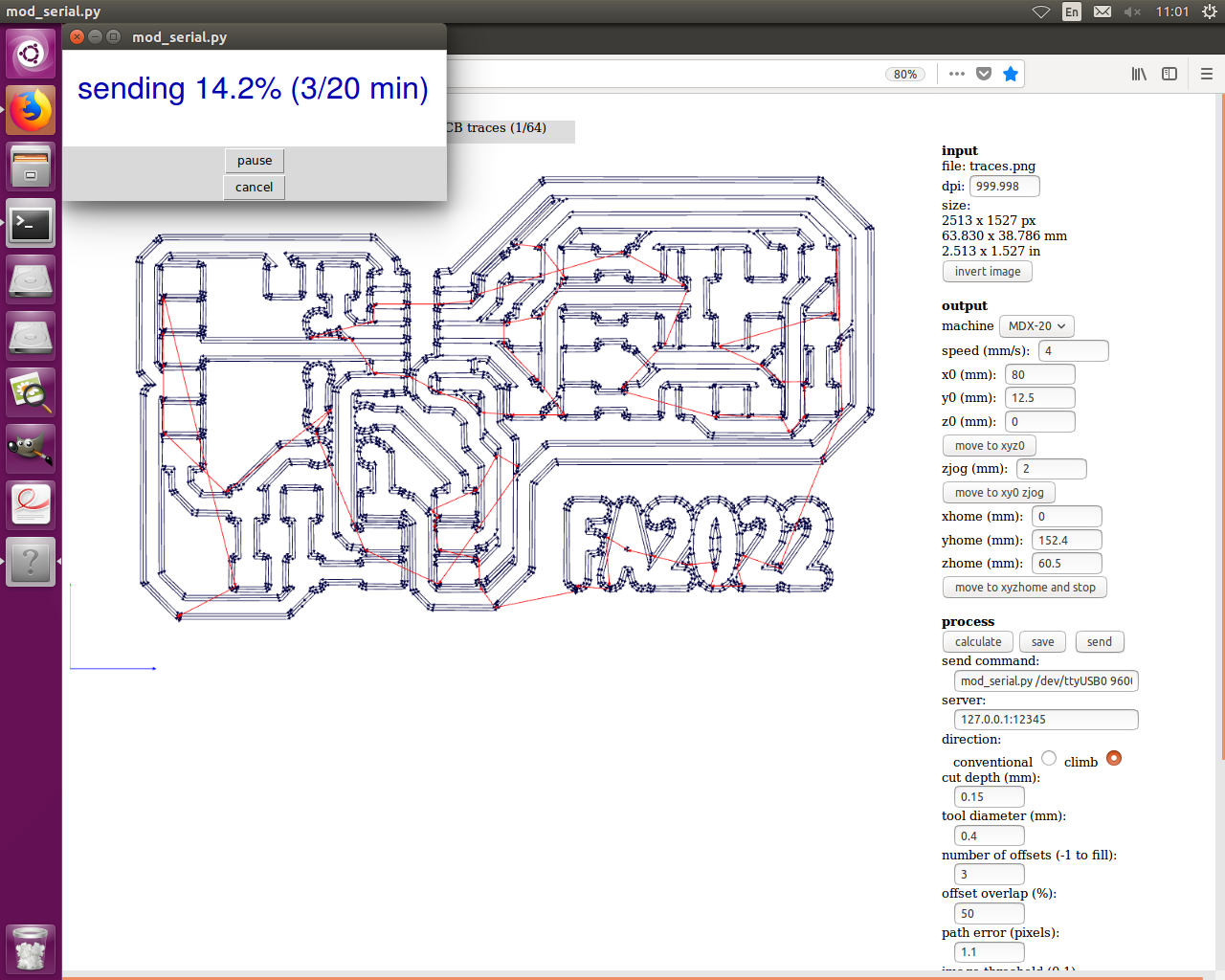
- Now open firefox and paste the IP address in the url to open the fab modules blank page. Then select Image PNG from the drop down menu.
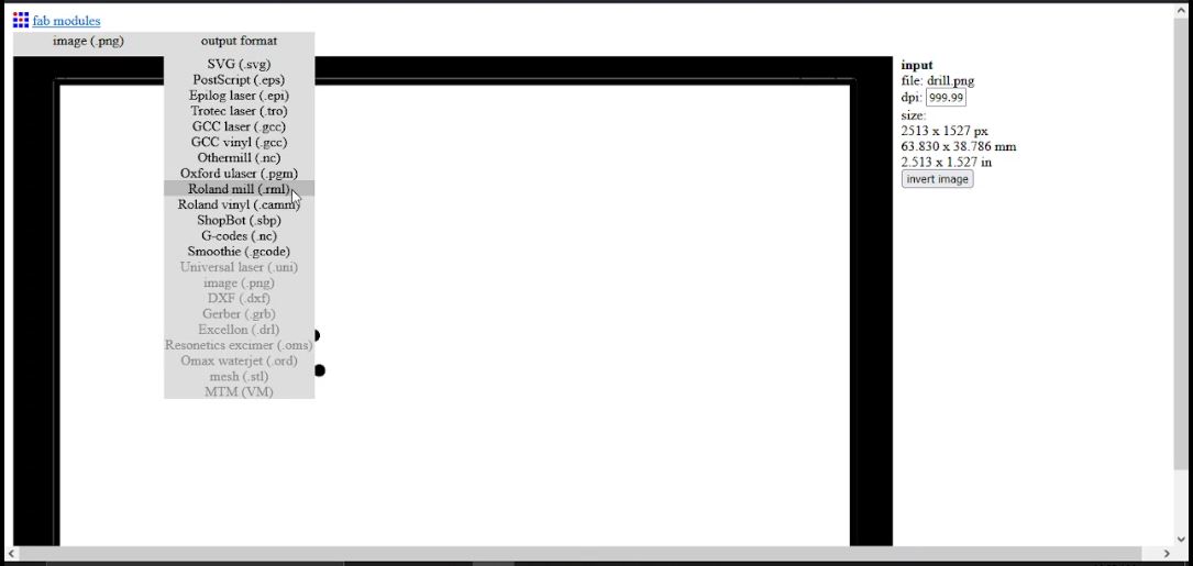
- Choose traces or drill PNG file from the final folder, then in the Output format drop down menu choose Roland mill (.rml).
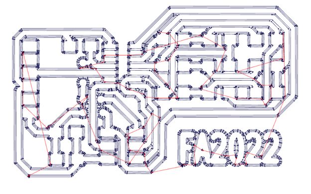
- As for the process select for trace file PCB traces (1/64) and for the drill file PCB outline (1/32) this process indicates the process and type of the bit .
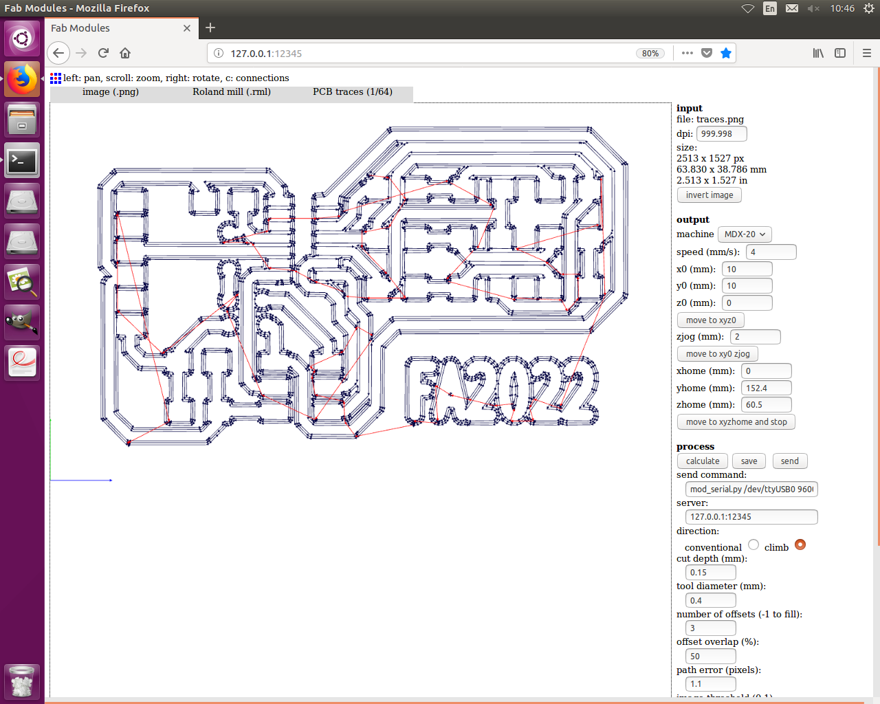
- Now check the dpi, it should match 1000 dpi or 999.998 to obtain an accurate size of the pcb. Also choose from machine drop down menu mdx-20 in the output, then leave the positions for later and change the cut depth to 0.15 (if the bed is uneven it will still give fine results). Also reduce number of offsets to 3. Everything Else should be fine but still have a look from top to bottom. Finally select calculate.
- Now complete the second process and then finally click Send
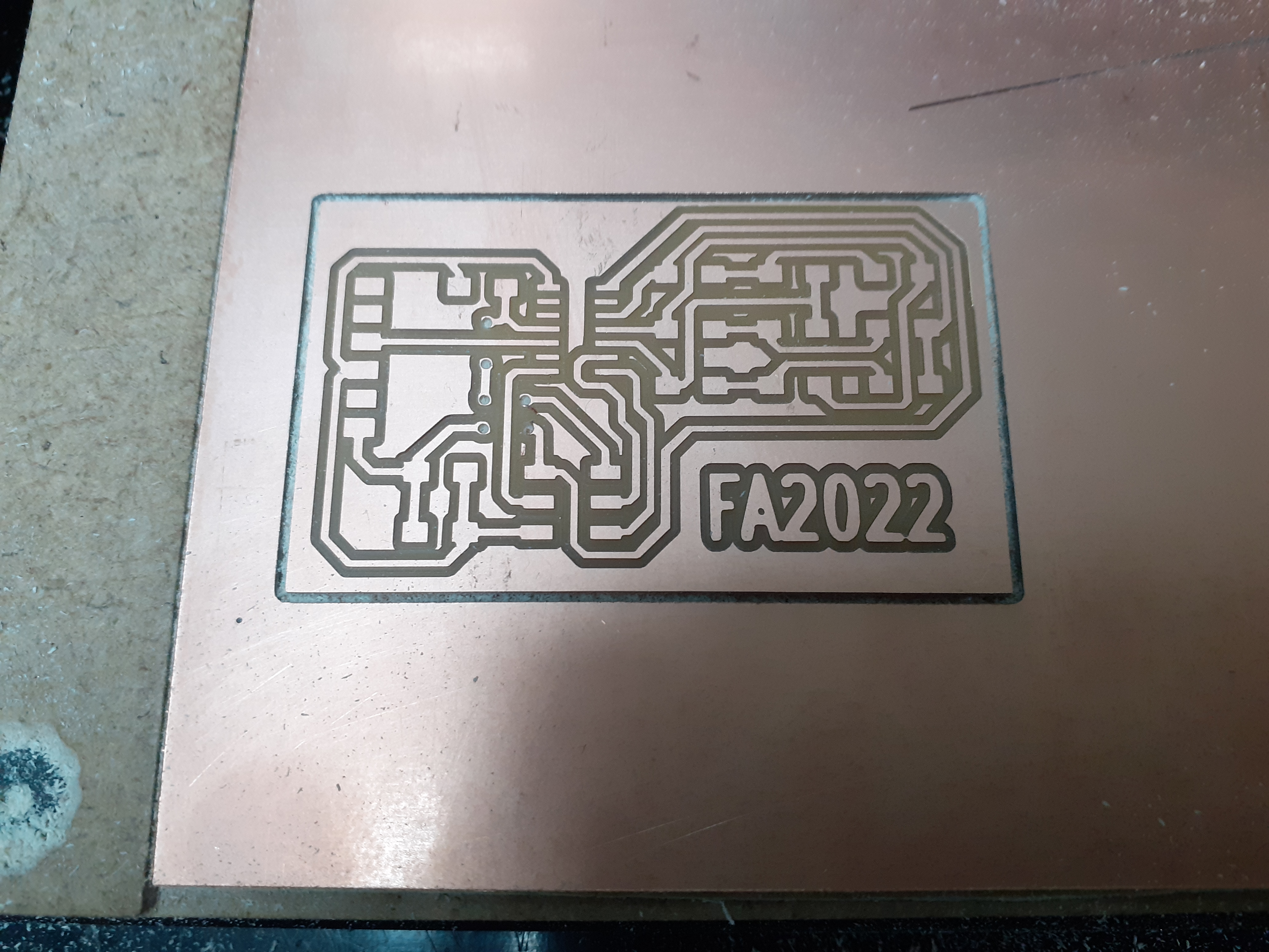
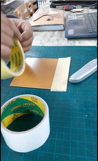
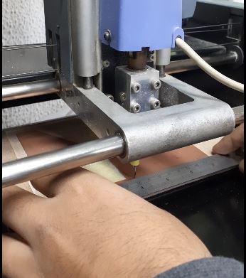
- Prepare a single layer PCB board with paint tape and double face.
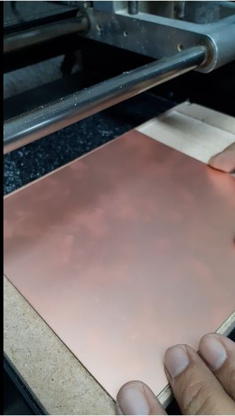
- Fix the PCB board on the sacrificial layer of the bed.
- Remove from view mode by pressing the view button.
- Fix the 0.4 v-bit in the spindle with the allen key provided with the machine for the traces process. Gently unscrew the nut a little bit and tighten it again after fixing it in place.For the drilling process change to 0.8 flat head bit. Don’t forget to keep both bits a little upwards as the bits do not break due to movement.
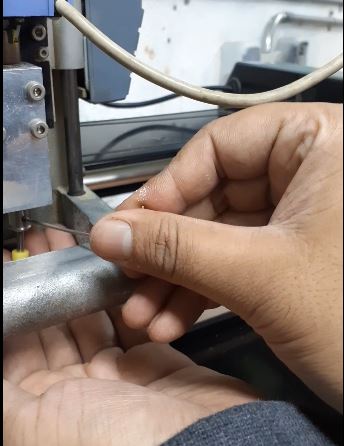
- To move the X and Y to the bottom left corner of the board, On the computer estimate the movement needed and write it in the x0 (mm) and y0 (mm) and keep the z0 (mm) as it is = 0, then click move to xyz0 tab. As for the Z axis, press the down button on the machine. Keep going down until the bit is above the pcb by 2-5 mm and still has the ability to move 4-5 mm downwards.
- Now gently unscrew the nut and let the bit touch the pcb by falling on it freely and tighten the nut again to secure its new place.
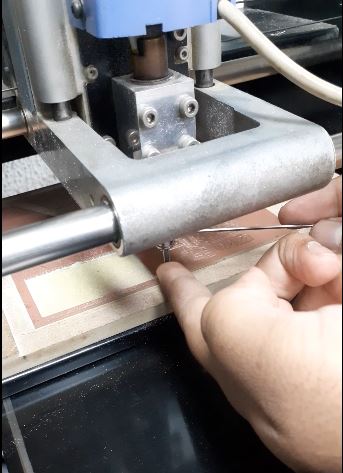
- Now click Send on the computer as mentioned in the previous process. It will now show the indication of and time for the running process
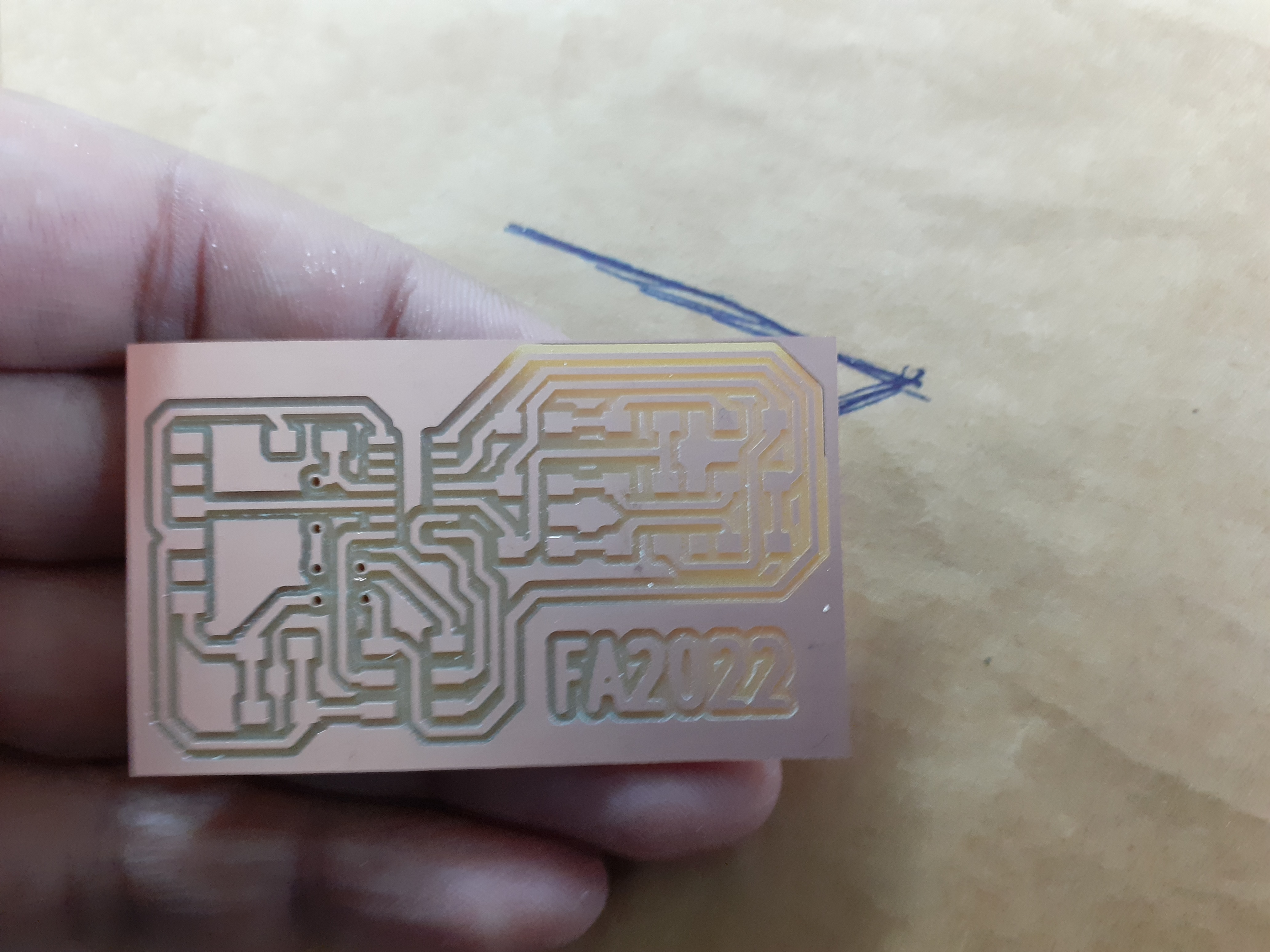
Done. Superb! Good job.